
S-Plan Wiring Guide
What Is S-Plan?
S-plan is the most common heating system wiring arrangement for properties with a separate hot water cylinder. It uses two independent 2-port motorised zone valves — one for the central heating circuit, one for the hot water cylinder — allowing both circuits to operate independently.
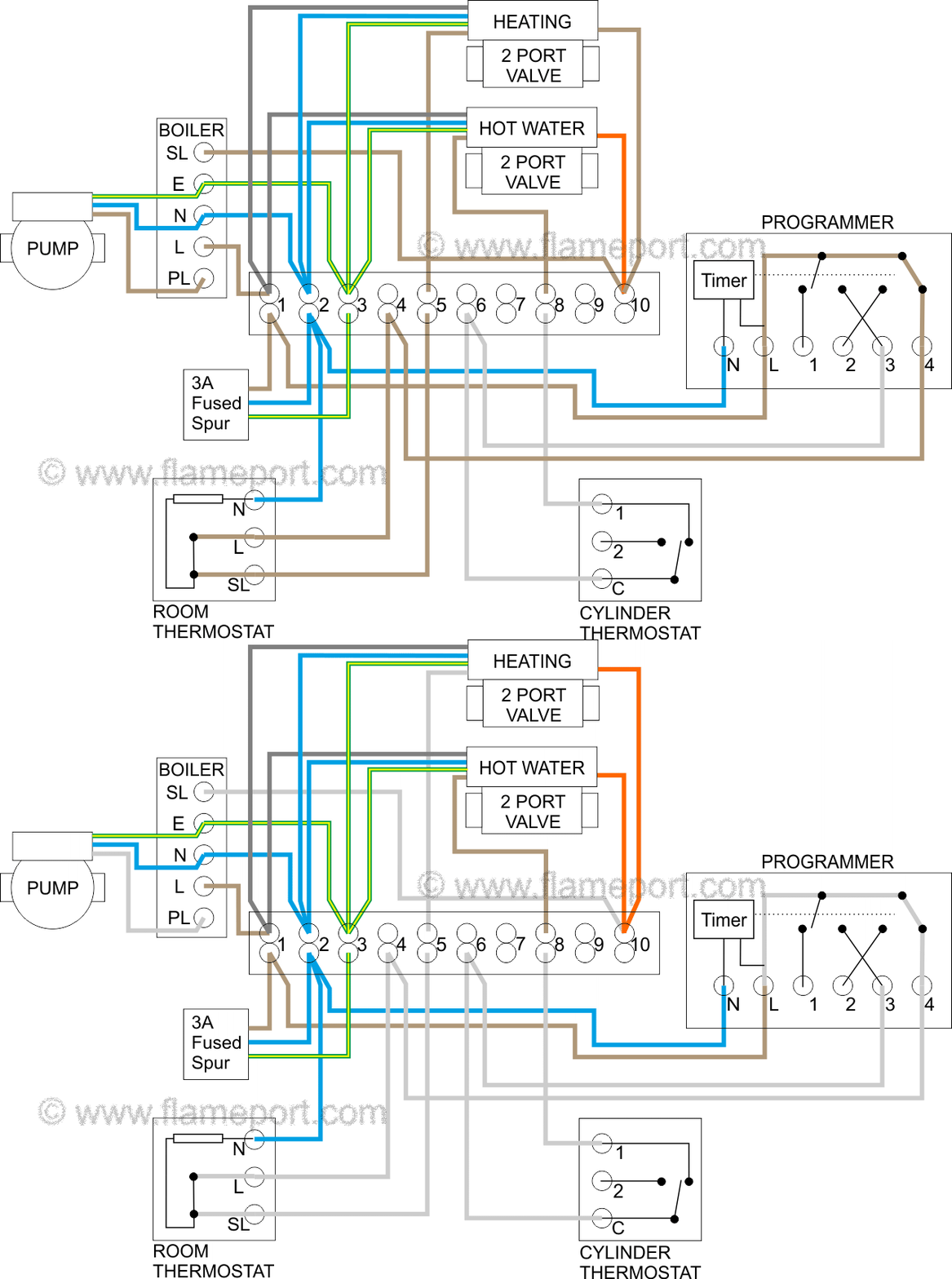
S-plan wiring: two 2-port zone valves, boiler, cylinder thermostat, and room thermostat. Source: flameport.com
System Components
| Component | Function |
|---|---|
| Room thermostat | Controls the central heating zone valve |
| Cylinder thermostat | Controls the hot water zone valve |
| Programmer / time clock | Sets on/off schedules for heating and hot water independently |
| 2-port zone valve (heating) | Opens to allow flow to the radiator circuit |
| 2-port zone valve (hot water) | Opens to allow flow to the hot water cylinder |
| Boiler | Fires when at least one zone valve is open and signalling demand |
How It Works
- The programmer allows heating and/or hot water to call for heat
- The room thermostat (heating) or cylinder thermostat (hot water) signals demand
- The relevant zone valve motor runs to the open position
- The zone valve's auxiliary switch closes — completing the circuit to fire the boiler and pump
- When demand is satisfied, the zone valve closes
- When all zone valves are closed, the boiler and pump stop
If only one zone is calling, only that valve opens — the boiler fires for that zone only.
Zone Valve Wiring
Standard 2-port zone valve wiring (Honeywell/Drayton pattern — most common):
| Terminal | Wire colour | Function |
|---|---|---|
| N | Blue | Neutral |
| L | Brown | Permanent live — powers the valve motor |
| Aux | Grey | Auxiliary switch — one side of volt-free contact. Typically fed with permanent live. |
| Aux | Orange | Auxiliary switch — other side of volt-free contact. Typically the switched live output to the boiler/pump demand. |
| Earth | Green/Yellow | Earth |
The auxiliary switch is a volt-free contact between grey and orange. It can be used as:
- Mains switching (most common): Permanent live fed into grey; when the valve fully opens, the aux switch closes and orange becomes a switched live — this fires the boiler
- Low-voltage / volt-free switching: Grey and orange used as a dry contact for low-voltage demand inputs
The aux switch only makes when the valve reaches the fully open position — ensuring the boiler only fires when water is actually flowing through the zone.
Replacing Controls on an S-Plan System
When fitting a Heatmiser neoStat on an S-plan system:
- Photograph the existing wiring before disconnecting anything
- Isolate at the consumer unit
- The neoStat replaces the room thermostat — wire neoStat SL (switched live) output in place of the old thermostat's switched live to the heating zone valve motor live terminal
- Do not disturb the cylinder thermostat or hot water zone valve wiring
- Power up and confirm the boiler fires when the neoStat calls for heat and the zone valve opens
Safe Working
- Isolate at the consumer unit before working — heating controls are typically on a 3A or 5A fused spur
- Photograph existing wiring before disconnecting anything
- Zone valve motors carry mains voltage — always isolate before disconnecting terminals
- Never work on gas connections, the boiler heat exchanger, or burner