
Pixel LED Lighting — Requirements, Wiring & Limitations
Addressable "pixel" LED strip (each individual LED, or small group of LEDs, is separately controllable — chases, colour gradients, per-pixel effects) is a different product from simple RGB/RGBW "dumb" strip, and it is wired differently. Confusing the two on site is the single most common source of mistakes:
- Dumb RGB/RGBW strip: 2 or 4 wires (V+ and one wire per colour channel). Any length of run just needs V+ and 0V/channels connected — no data signal, no controller-per-run requirement, no resistor, no chain order.
- Pixel/addressable strip (WS2812, WS2814, SK6812, etc.): needs V+, 0V, and a DATA signal that must originate from a controller and travel down the strip in one continuous chain, in order, with correct polarity.
This guide covers pixel strip only. The worked example throughout, and the attached diagram, is a real installed job (Job 5508, Lowther Lodge) — see Worked Example at the end.
System Overview
| Component | Role |
|---|---|
| PSU (24V typical) | Powers strip + controllers. Sized per zone/run, never shared across unrelated circuits without checking combined load. |
| Zone controller (e.g. MiBoxer SPIR5) | Generates the DATA signal for one run. One controller per independently-addressable zone. Receives commands via RF from a wall panel and/or WiFi gateway. |
| Wall touch panel (e.g. MiBoxer B9) | User control point. Pairs to multiple controllers via 2.4GHz RF — confirm panel/controller family compatibility before speccing (see Limitations below). |
| WiFi gateway (e.g. MiBoxer WL-Box2) | Bridges the RF ecosystem to the vendor's app/voice control. Optional — the wall panel works standalone without it. |
| Pixel LED strip | Confirm the chip (WS2814 supports RGBW; WS2812/SK6812 vary) matches what the controller is rated for, and that indoor (IP20) vs outdoor (IP68) product is correctly specified per location. |
| In-line resistor (220-470Ω) | Fitted on the data line at the controller end. Standard practice, not optional — prevents the first pixel misreading the initial data edge. |
PSU Sizing and Circuits
- Size each PSU to the combined load of everything it feeds, with real headroom (30-50%+), not run flat out. A PSU feeding two 8m pixel runs at ~45W each wants meaningfully more than 90W of capacity.
- PSU to controller is always a home run — one dedicated cable per controller, straight back to the PSU. Never daisy-chain 24V power from one controller's terminals to the next controller. Daisy-chaining compounds volt drop unpredictably and means one bad joint takes out every downstream zone.
- Indoor and outdoor circuits should be on separate PSUs even if physically close — they're genuinely separate zones with separate strip products (see Indoor to Outdoor Transition below), and this also keeps a fault in one environment from affecting the other.
PSU to Controller Cabling
1.0mm² 2-core (V+, 0V) is normally sufficient, but check the actual current draw and run length for the job in hand — don't copy a cable spec from a different job's figures without recalculating.
Worked figure from Job 5508: 1.0mm² verified safe to ~18m one-way at 1.87A (the highest-current indoor zone) before exceeding 5% volt drop. A lower-current outdoor zone was safe well beyond that at the same CSA. If a run is longer, or the zone draws more current, step up the CSA and recheck the volt-drop sum.
Controller to Strip Cabling
- Position the controller within about 3m of the physical start of the strip run where possible, concealed in the same void the strip/profile sits in.
- Under roughly 3m, ordinary alarm/bell cable is fine for the data run — no shielding or signal level-shifter needed at that distance. Beyond that, data integrity becomes a real risk and needs proper consideration (better cable, a repeater/level-shifter, or repositioning the controller).
- Use 3 cores from a 6 or 8-core cable: V+, 0V, DATA. Physically twist or pair the DATA core alongside a ground core — this materially helps signal integrity, it isn't cosmetic.
- Fit the 220-470Ω resistor in-line on the data core, at the controller end.
Joining Strip Reels Mid-Run
Real strip reels come in fixed lengths (commonly 5m), so an 8m run needs two physical pieces joined. Two extra rules beyond a normal splice:
- One continuous data chain per run, never two. At the joint, solder V+, 0V, and DATA straight through. Do not terminate one section's data output and start a fresh data input on the next section as if it were two independent runs.
- Add a power-only tap at the joint, sourced locally from the controller (not run all the way back to the PSU), to cover the volt drop the joint would otherwise accumulate over the full run length. This tap carries V+ and 0V only, no data — typically 6-core cable with the cores tripled (3 for V+, 3 for 0V). It only needs to carry roughly a third of the zone's total current, since the two ends of the run now share the load between them.
- Cut reels exactly on the marked pixel-pitch line at the joint, and use strip from the same batch where possible — cutting off-pitch or mixing batches shows up as a visible dark gap or tint shift right at the splice.
Indoor to Outdoor Transition
Where a lighting scheme genuinely runs from an indoor space to an exterior feature, treat the crossing point as a deliberate physical and logical break, not a fault to route around:
- Different strip product either side (IP20 indoor vs IP68 outdoor) — not the same item, don't order as if they were.
- Separate zones/controllers either side, not one continuous data chain crossing the building envelope.
- Fit a proper weatherproof gland/grommet exactly at the crossing point, regardless of how short the exposed run looks.
Wall Panel / Accessory Power Supply
- Check the panel manufacturer's own installation manual for its specified accessory PSU — don't assume a wall panel can be powered informally from a nearby low-voltage source. MiBoxer's B9, for example, explicitly requires their PER1 accessory PSU (AC in, DC3.3V/200mA out), bought and fitted as a real component, on its own fused spur at the DB.
- Repurposing an existing lighting/switch cable run as the panel's DC feed is a legitimate approach — live and neutral cores become DC+/DC-, earth left unused — provided volt drop is checked against the panel's actual rated current at the real distance.
- RF pairing, not wired data, links the panel to the controllers on systems like this — check the specific link procedure in the panel's manual. One wall panel can typically pair to many controllers; don't assume one panel per zone.
Limitations & Common Pitfalls
⚠️ Never daisy-chain PSU power between controllers. Always home-run each controller back to its PSU.
⚠️ Never split a run's data into two independent chains. Solder straight through at joints; handle volt drop with a separate power-only tap, not a second data start.
⚠️ Don't assume controller and wall panel families are interchangeable. Confirm compatibility on the manufacturer's own product page before ordering. On Job 5508, MiBoxer's SPIR5 controller is confirmed compatible with the B9 panel, but the SPIR3 + B6 pairing found in earlier research is a different, non-interchangeable pairing — don't mix SPIR3 controllers with a B9 panel.
⚠️ Don't assume a colour channel exists just because a sibling product documents it. A manufacturer's manual may not explicitly confirm a feature (e.g. a dedicated white channel) for the exact model being fitted, even where a closely related model in the same range documents it. Treat this as reasonable to proceed on, but verify with a bench test before the customer sees it.
⚠️ Confirm real on-site cable distances before finalising cable CSA and ordering quantities. Volt-drop figures in this guide are valid for the specific current and distance they were calculated against — recalculate for a different job rather than reusing a number.
⚠️ Confirm strip reel lengths with the actual supplier before finalising an order, especially for outdoor/IP68 product where reel lengths vary more between suppliers than standard indoor 5m reels.
Worked Example: Job 5508, Lowther Lodge Summer House
8 independently-zoned addressable pixel LED runs: 4 indoor (ridge/eaves either side of a structural steel, vaulted ceiling), 4 outdoor (glass triangle feature), on a MiBoxer SPI ecosystem (SPIR5 controllers, B9 wall panel, WL-Box2 WiFi gateway).
| PSU | Feeds | Combined load | Headroom |
|---|---|---|---|
| PSU-A (indoor) | Run 1 + Run 2 | 90W | 40% |
| PSU-B (indoor) | Run 3 + Run 4 | 90W | 40% |
| PSU-C (outdoor) | Runs 5-8 | 68W | 55% |
Indoor runs are 8m each, built from a 5m reel joined to a 3m cut length using the mid-run-joint technique above (continuous data, local power-only tap). Outdoor runs are 3m each, single reel, no joint needed.
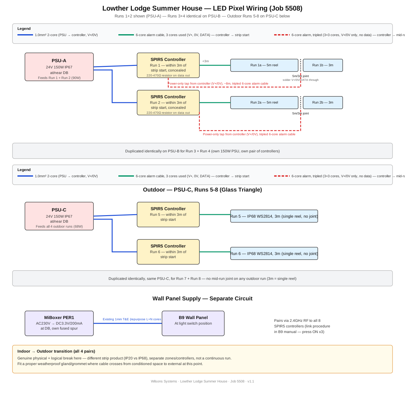
Full wiring diagram, PSU-A/B (indoor, Runs 1-4) and PSU-C (outdoor, Runs 5-8). Wilsons Systems, Job 5508.